Why not use Link Aggregation to extend your Network?
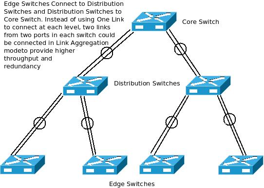
Link Aggregation Architecture Diagram:
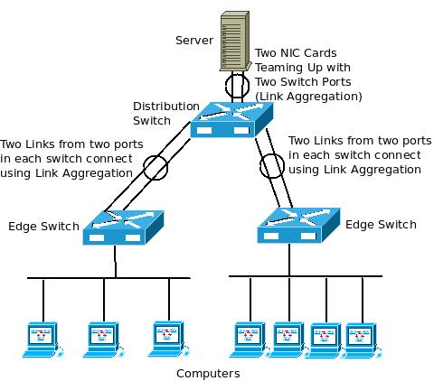
Extending your network using Link Aggregation:
 Link Aggregation and its advantages:
Link Aggregation is a very useful method to combine multiple links to form a single (bigger) link. It can be either two links from two ports of each switch connecting to another switch as shown in the above diagram, or multiple links from multiple ports. Similarly, two (or more) links from two (or more) ports from a server can also connect to two (or more) switch ports to form a bigger link.
The main advantage of doing this is the higher capacity obtained from each group of aggregated links. For example, if two 1 GE ports from two switches connect to each other using Link Aggregation, we get a single virtual 2 GE port. In case you want to upgrade the network backbone, this method of connecting the switches using Link Aggregation not only uses the existing switches, but also gives a 2x,3x… higher backbone throughput. Compare this with replacing all the switches with newer ones and getting a 10x increase in throughput which may not be fully utilized.
More importantly, as multiple links connect from one switch to another using Link Aggregation, if one link fails, the traffic would continue to flow through the other link(s). So, this gives cable level redundancy for all the interconnections made using Link Aggregation protocol. You can Link Aggregate two copper links (or) two single more fiber links (or) two multi mode fiber links (a combination of copper/ fiber is not allowed though). All the aggregated links need to operate at the same speed (100 Mbps or 1GE or 10GE).
Link Aggregation can also do load balancing among the various links in the Link Aggregation Group. So, the traffic is split evenly between the various links which ensures its effective utilization.
With Link Aggregation, each individual link can be configured to carry a separate class of traffic (like voice) if desired, using QoS parameters. Each individual link can also be configured to carry traffic from particular node(s)/server(s). This enables a separate un-congested route for important / latency sensitive applications/ nodes.
Even Switches from different vendors can be used to form a Link Aggregation Group as long as they support IEEE Standards – 802.3ad/ 802.1AX.
Link Aggregation can also be applied in virtual server environments, where it is possible to connect ports in a single virtual switch to multiple physical Ethernet adapters thereby giving a higher throughput (than connecting just a single adapter). Even load balancing is supported in such configurations by certain server virtualization solutions.
LACP (Link Aggregation Control Protocol):
Dynamic Link Aggregation uses LACP (Link Aggregation Control Protocol) which enables the switches to know which switches connected to them are configured for interoperability using Link Aggregation. LACP can exchange configuration information among cooperating systems and automatically detect the presence and capabilities of other Link Aggregation capable devices.
LACP makes it easy to identify any cabling or configuration mistakes while configuring Link Aggregation between two devices. It is also possible to specify which links in a system can be aggregated, using the Link Aggregation Control Protocol (LACP).
Limitations of Link Aggregation:
Link Aggregation occupies additional switch ports which can otherwise be used to connect the nodes/systems.
Link Aggregation accounts for only cabling failures but does not give redundancy in the case of switch failures (although some proprietary vendor implementations can achieve this).
Link Aggregation cannot itself prevent any loops from occurring in the network.
There is a maximum limit to the number of links in each Link Aggregation Group (LAG) and it is generally specified by the vendor (generally eight).
excITingIP.com
You can stay up to date with the various computer networking technologies by subscribing to this blog using your email address in the box mentioned as “Get Email updates when new articles are published”.

Excellent write up but like every other place I’ve found, you barely mention anything at all about the load balancing. I am desperate to find some more information on how the actual load balancing works. I understand that your creating a LAG and a virtual port that consists of all of the aggregated switch ports, and that the LAG will only allow the max cap of the single port speed to transmit to an end point/client so the gain is said to be when you are transferring data between multiple clients. BUT HOW is that a gain? I was really hoping for some load balancing examples of real world gains/benefits through any method of utilizing LACP and aggregation for load balancing, have anything? If you can only send/receive at 1 G on a 1 G port how does using LACP to aggregate 2 ports between 2 switches in a LAG become capable of 2G bandwidth help anything? Have an example?
Hello Medryn,
The load balancing issue is one of the main problems LACP does NOT fix, as compared to static link aggregation. It is up to the switch to deside which link to use for a new connection.
SMB3 (i.e. windows 2012 – windows 2012) file copy should benefit from LACP.
With prices of 10Gb starting to come down, I’d use 10Gb in stead of link aggregation.
Directly from the HP K/KA/KB.15.15 manual:
With a recent firmware, you can configure the load balancing methode on procurve 3500/3800/5400/8200 switches:
Enabling L4-based trunk load balancing
Enter the following command with the L4-based option to enable load balancing on Layer 4
information when it is present.
Syntax
trunk-load-balance [ L3-based | L4-based ]
When the L4-based option is configured, enables load balancing based on Layer 4 information
if it is present. If it is not present, Layer 3 information is used if present; if Layer 3 information is
not present, Layer 2 information is used. The configuration is executed in global configuration
context and applies to the entire switch.
Hi,
I want to know the aggregated capacity. E.g. I heard 2 x 1G aggregated links can give you at most 1.4 G – 1.6 G (70% – 80%) of the aggregated links. Is this true?
In short, I want to confirm if aggregated links give us the same capacity or does it reduce the capacity?
BR
Masud
Hi,
I believed that’s true…LAG would definitely not giving 100% capacity, I would say around 65%-85% that can only be used…this also depends on the type of applications/service you’re carrying through the LAG links as smaller MTU sizes will definitely reduced the total capacity that can be used…
I’m also looking for others input and comments on this matters… Thanks
I have done extensive testing with Ixia equipment and LAG groups. For two physical ports, the typical throughput is 1.2 to 1.8 times the speed of a single link. What defines the efficiency is the hash algorithm and the diversity of the traffic. The Source/Destination of the IP/MAC/UDP ports are frequently ExORed (exclusive Or’ed) together to decide whether the frame/packet travels over link one or link two in the LAG. The actual standards do not define a specific algorithm, so each switch vendor is free to skin the cat a different way without violating the standard. Some vendors do it better than others. But, the most critical factor is the diversity of the traffic which is traversing the LAG. If there are not some significant differences, you can end up with one link at 100+ percent (meaning discarded traffic), while the other link is only at 20%. Most of the algorithms only work well with binary multiples of 2 for port count in the LAG. i.e. 2/4/8 ports are good, and 3/5/6/7 are quite bad (lower hashing efficiency). What gets really ugly is when a single link fails, in a LAG of 4 or 8. The majority of switch manufacturers simply take ALL of the traffic which was on the failed link, and entirely dump it on another of the remaining links. This means when the rest of the links are running at 50ish percent, the double-subscribed link is slightly oversubscribed and discarding traffic. The 8 Gig Lag, in this scenario is performing about the same as a 4 Gig Lag.